


System Integration & Software ManagementCapability
SYSTEM INTEGRATION & SOFTWARE MANAGEMENT
Mowe has been proudly involved in comprehensive system integration and software development for the past 20 years over many onshore and offshore projects.
SYSTEM INTEGRATION & PLATFORMS
Our team of engineers is proficient in designing and integrating systems solutions to client's specifications in Marine, Oil & Gas, and Power industries. We deliver customized solutions in terms of size, pressure, and other engineering parameters to major oil and gas customers.
Our delivery of several FSO, FPSO, Platforms and Jack ups in terms of marine, offshore and top side packages to clients are well in service till today.
PETRONAS HPHT SYSTEM
Our engineering delivery of HPHT system at 15,000 psi and flow rate controlled at 1.3 Litre per hour which equates to 0.021 Litres per minute is still our most challenging task till today and of a pinnacle project till today with Petronas.

OUR DELIVERY INCLUDES
Design & Engineering
Complete design and engineering to meet project specifications.
Project Management
End-to-end project management from planning to execution.
Factory Acceptance Test
Comprehensive FAT to ensure system performance and reliability.
Site Acceptance Test
SAT and offshore hook-ups to ensure successful commissioning.
Commissioning
Final commissioning and support to ensure smooth project handover.
We deliver solutions to customers and work hand in hand with them earnestly form design, project management, Factory Acceptance test to the final stages of Site Acceptance test and offshore hook-ups and commissioning.

We obtained good references from Shell, FPSO Ventures, Petrofac and many other major customers.
PETRONAS HPHT & KINABALU NAG PHASE II
HIGH PRESSURE HIGH TEMPERATURE (HPHT) INJECTION SYSTEM | OFFSHORE SABAH | 2012–2016
MOWE Marine & Offshore engineered and delivered specialised, high-precision fluid control and chemical injection solutions for demanding offshore oil & gas applications, including the PETRONAS HPHT System and the Kinabalu Non-Associated Gas (NAG) Development Project – Phase II at the KNPG-B Central Processing Platform, offshore Sabah, Malaysia.
These engineering applications involve high-pressure fluid injection, precision low-flow regulation, pressure containment, chemical compatibility and reliable system integration under demanding offshore operating conditions.
KEY TECHNICAL DATA
ENGINEERING SCOPE & TECHNICAL CHALLENGES
Delivering specialised injection systems for offshore operations requires precise engineering, careful component selection and dependable integration. MOWE's engineering approach addresses demanding pressure requirements, controlled chemical dosing, corrosion considerations and platform installation constraints.
- HPHT System Design – Engineering solutions for high-pressure applications up to the specified 15,000 psi.
- Precision Micro-Flow Control – Controlled injection rates of approximately 1.3 L/h (0.021 L/min), subject to the applicable system operating conditions.
- Chemical Injection Skid Packages – Integration of project-specific chemical management and injection equipment.
- Flow Control & Metering – Integration of Injection Rate Control Devices (IRCD) to support accurate chemical dosing.
- Pressure Containment & Hydraulic Integration – Selection and integration of pressure-rated valves, tubing, fittings, instrumentation and flow-control components.
- Corrosion Resistance & Asset Integrity – Material selection based on pressure ratings, chemical compatibility, CO₂ exposure and marine operating conditions.
- Compact Offshore Integration – Space-conscious equipment arrangements to support topside footprint and installation requirements.
- Testing & Commissioning – System verification and commissioning in accordance with applicable project specifications.
MOWE ENGINEERING CAPABILITY
MOWE Marine & Offshore provides engineering, fabrication, system integration and testing solutions for specialised marine, offshore and oil & gas applications. These projects demonstrate our capabilities in high-pressure fluid injection, chemical management, precision flow regulation and project-specific hydraulic system integration.
Our engineering approach brings together component selection, pressure-rated equipment, instrumentation, tubing, fittings and control elements to develop integrated solutions based on project specifications and operational requirements.
PROJECT SIGNIFICANCE
The combination of high-pressure operation up to 15,000 psi, precision low-flow injection, chemical compatibility and offshore integration highlights the engineering demands of specialised HPHT and chemical injection systems. Through these applications, MOWE demonstrates its commitment to reliable engineering solutions for challenging marine, offshore and oil & gas environments.
SOFTWARE DESIGN & DEVELOPMENT (SCADA / PLC / HMI) +
Mowe is capable of designing and developing a complete automation solution for process applications according to customer demands and specifications.
SCADA / PLC / HMI systems are not only used in Oil & Gas industries, they are also controlled solutions for all other industries like pharmaceutical, buildings, civil, mining, aviation and works with heating, valve automation, instrumentation, solar and other mechanical / measuring equipment.


SCADA, PLC and HMI Works Hand-In-Hand...
Supervisory Control And Data Acquisition (SCADA) is a control system capable to perform a supervisory operation over large-scale processes that can include multiple sites, and work over large distances as well as small distances.
SCADA system also have a huge capacity for data collection, and process data faster and with accuracy, and allow smooth communication between various parts of the system.
SCADA system comprising of both hardware elements like computers, and software elements like networked data communications and Graphical User Interfaces (GUI) for high-level process supervisory management, while also comprising other peripheral devices like Programmable Logic Controllers (PLC) and discrete Human Machine Interface (HMI) controllers to interface with process plant or machinery.


MAIN ELEMENTS OF A SCADA SYSTEM

1. SUPERVISORY COMPUTERS
The core of the SCADA system, gathering data on the process and sending control commands to the field connected devices. It refers to the computer and software responsible for communicating with the field connection controllers, which are RTUs and PLCs, and includes the HMI software running on operator workstations.

2. REMOTE TERMINAL UNITS (RTUS)
Connect to sensors and actuators in the process, and are networked to the supervisory computer system. RTUs have embedded control capabilities and often conform to the IEC 61131-3 standard for programming and support automation via ladder logic, a function block diagram or a variety of other languages.

3. PROGRAMMABLE LOGIC CONTROLLERS (PLCS)
Connected to sensors and actuators in the process, and are networked to the supervisory microcomputer system. This powerful microcomputer monitor the state of input devices which are directly connected to the PLCs and makes decisions about controlling the state of output devices to either energize or de-energize them.

4. HUMAN-MACHINE INTERFACE (HMI)
HMI are local machines. HMI is an operator window of the supervisory system that allows the operator to interact with the controlled system or device. It presents plant information to the operating personnel graphically in the form of mimic diagrams, which are a schematic representation of the plant being controlled, and alarm and event logging pages.

5. SCADA DIAGRAM / HMI DIAGRAM
A SCADA Diagram / HMI diagram can be as simple as a few pages to hundreds pages. From simple design as a Hot Water Calorifier package to complex systems as Emergency Shut Down Valve system (ESDVs) and other process packages.
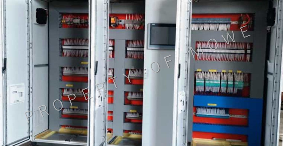
6. SIEMENS PROFIBUS NETWORKS MANUAL
Supports reliable communication between field devices and control systems using Siemens Profibus network standards.
DOWNLOAD MANUAL PDF →
OPERATIONAL EFFICIENCY

REMOTE CONTROL
Enable integrated control of multi-platform systems / processes from a remote location or locally.

HMI INTERFACE
Interaction with sensors, pumps, motors, and valves through an HMI (Human-Machine Interface) software.

SIMULATION
Simulation.

VISUAL DISPLAY
Vivid visual display and presentation for good understanding.

SECURITY
Security.

REDUNDANCY FEATURES
Reliable redundancy features.

EVENT LOGGING
Collecting and recording the events into a file.

BUSINESS ADVANTAGES
INCREASE SAFETY
Increase safety in operations e.g. automation startup and shutdown sequence.
REDUCE MAINTENANCE COST
Reduce long term maintenance cost.
REDUCE IMPLEMENTATION COST
Reduce implementation cost and increase efficiency.
EASE OF MAINTENANCE
Increasing ease of maintenance.